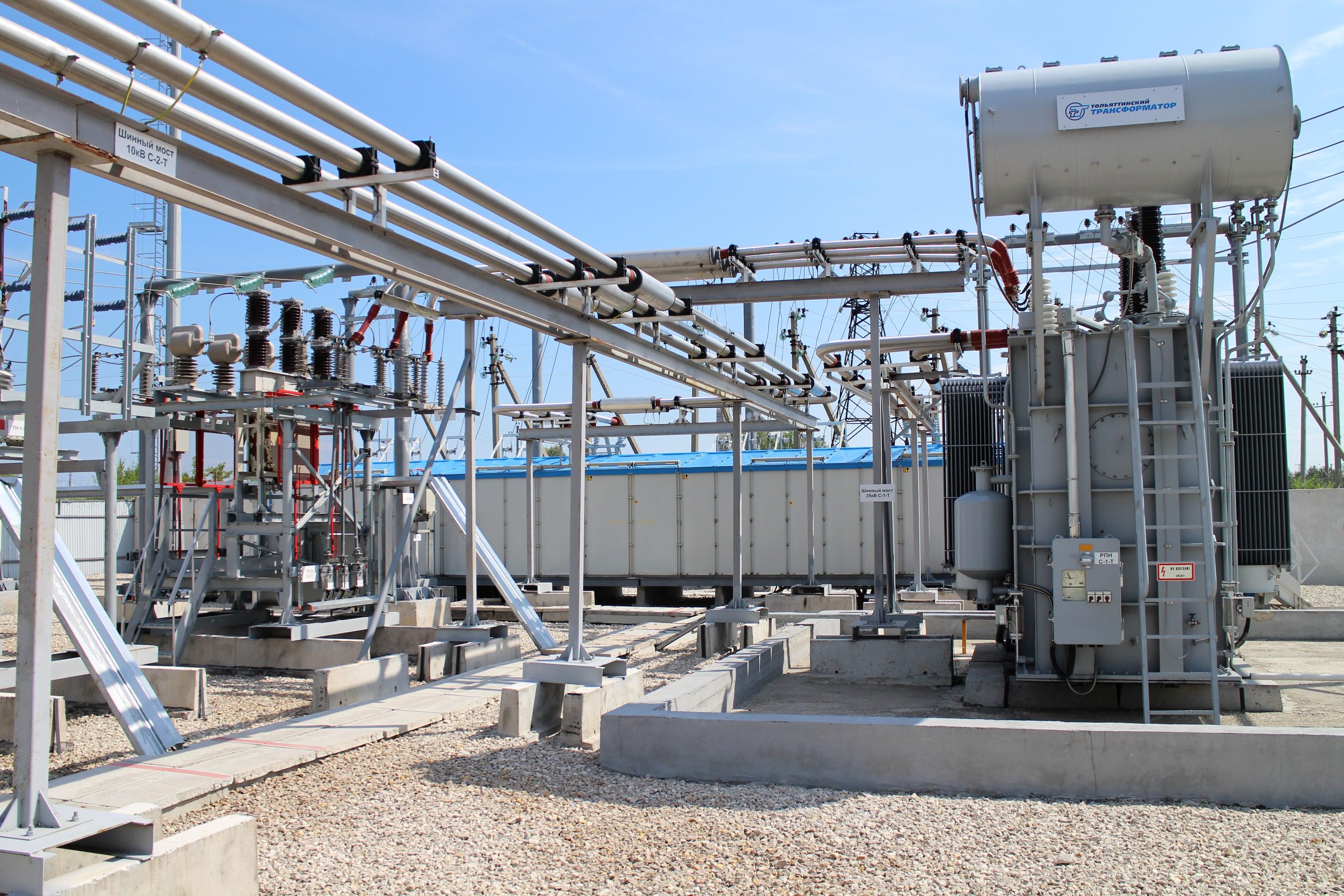
INTENDED USE
The solid insulated bus bar type ISOBUS/TPL is ideal for medium & low voltage safety-critical projects. ISOBUS/TPL is both electrically and geometrically made to measure according to project specifications. Up to 36 kV & 6 500 A per single phase is possible. For shorter generator connections, where space is very limited, it is possible to provide up to 36 kV & 12 000 A. Here we use 2 X bus bars per phase.
TECHNICAL SPECIFICATIONS
Low voltage systems:
| АС | DC | |
| Nominal voltage | up to 1,2 kV | up to 2 kV |
| Nominal current | up to 12 kА | up to 14 kА |
Medium voltage systems:
| АС | DC | |
| Nominal voltage | up to 40.5 kV | up to 60 kV |
| Nominal current | up to 12 kА | up to 14 kА |
FEATURES of ISOBUS/TPL
VIDEO
TYPE TESTS
In addition to in house routine testing our products have undergone rigorous type testing as follows:
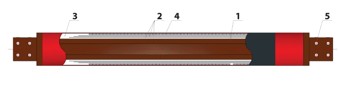
The bus bar element’s construction
|
The basic conductor tube (1) can be aluminum or copper & either solid or hollow, depending upon amperage. Then the conductor tube is then wrapped with crepe paper and layers of semiconducting paper (2) in order to provide the capacitive grading layers. During manufacture under vacuum, epoxy is pulled through to ensure a void-free partial discharge free composite dielectric (3). The embedded earth layer ensures that the system is touch-safe whilst operational (4). To make connections easy between Bus bar — bus bar and bus bar — other equipment, there is a DIN flat terminals (5) at the ends of each element.
For low voltage solid insulated bus bar type ISOBUS/TPL solutions up to 1.2 kV there are no capacitive grading layers & no earth layer required.
MANUFACTURE OF SOLID INSULATED BUS BAR TYPE ISOBUS/TPL VOID FREE, PARTIAL DISCHARGE FREE ACCORDING TO IEC 60137
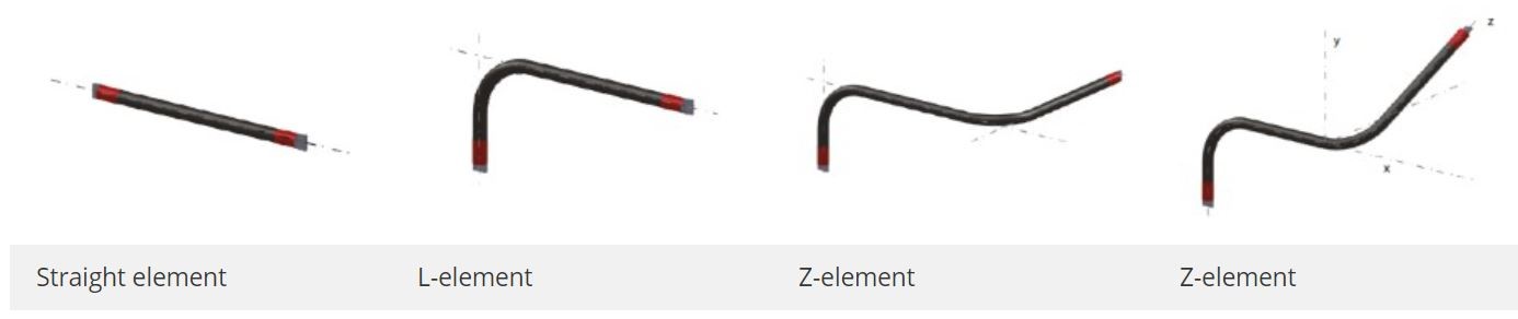
ISOBUS/TPL can be manufactured in lengths up to 10 meters long. The product is cured in an autoclave under vacuum & heat. The dimensions of the autoclave are 10 m × 2 m × 2 m. Almost any geometric shape is possible, below are some examples.
Measurement of specific resistance conductors & capacitors,
Pre-manufacture all raw materials quality checked
Curing in Autoclave is computer monitored
Electrical Testing of Bus bars & connecting sleeves
Internal Quality Checks
Bus bars have capacitive control, therefore, there is a red grading length on the ends. Separate bus bar elements are connected to each other by use of bus expansion compensators which are flexible copper laminate connections. These allow for thermal expansion & contraction. They also allow build tolerances of up to ±50 mm per connection.
The connection is then enclosed by a fully capacitive graded insulated connecting sleeve which has pressure-tight flanges on both sides. In order to balance the potential between the current carrying conductor and the internal surface of the connecting sleeve, a metal ring with contact spring are provided.
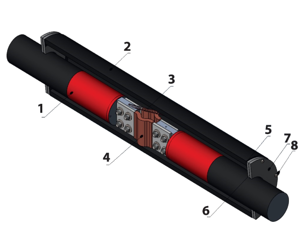
1. Busbar element
2. Connecting sleeve
3. Contact spring
4. Flexible
5. Flat washer
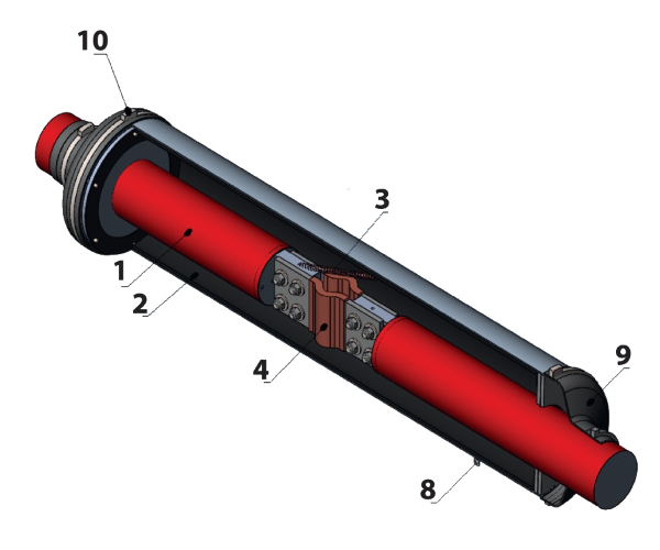
6. Sealing ring
7. Half flange
8. The connecting sleeve’s earthing
9. Bellows
10. Clamp
We use a special computer program to dimension the fixing system, taking into account short circuit current, natural frequency & weight.
The distance between the mounting places of the bus bar to the walls, ceiling or floor is calculated, prohibited distances are also calculated.
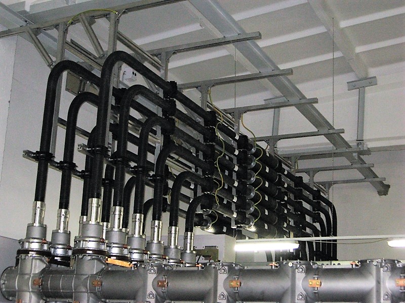
Fixation of the bus bar to the walls, ceiling or floors is carried out by means of polyamide clamps, aluminum x-profiles, fixing angles and hardware.
Mounting to a wall allows both horizontal and vertical installation of the bus bar. We can also mount to the floor where the project requires this.
ISOBUS/TPL FIREPROOF WALL PENETRATIONS
ISOBUS/TPL is compatible with any fireproof penetration which our clients require for their projects. In the example below, the penetrations are filled with a special noncombustible material and then closed using metal plates.
EARTHING OF THE BUS BAR
The bus bar equipment is individually earthed as follows, the bus bars, the connecting sleeves, and the fixing system. Then this can be connected to the main earth as shown in example photo below.
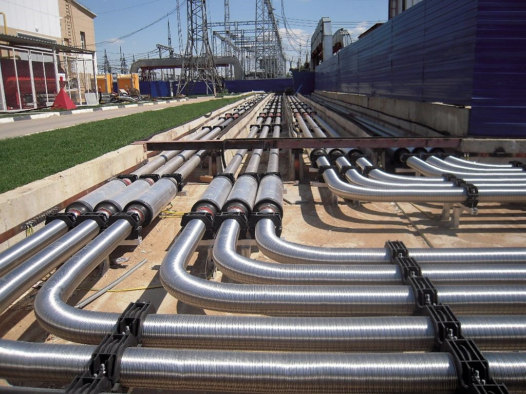
According to individual project specifications and requirements, we select the optimal bus bar path to ensure the safest shortest route.
Connections to other equipment can be from the top, the side, or underneath.
Generator & transformer connections are enabled using high flexible copper connections.
Protection boxes/special flanges can be supplied where necessary.
ADDITIONAL EQUIPMENT AND ACCESSORIES
Depending on the specification requirements, ISOBUS/TPL bus bar can be completed with additional electric equipment:
ISOBUS/TPL modular distribution kit is delivered on site complete with all components/documents required for installation.
The delivery package is created according to design documentation and rigorously checked prior to dispatch. The list below shows the main elements.
According to the design documentation bus bars & components are packed and fastened into wooden boxes.
The bus bar elements are fastened on pallets unwrapped, however, the ends with capacitive grading are protectively wrapped.
Separately delivered small size assembly units, details, and fasteners are packed into wooden boxes according to the design documentation.